")
")


Engine Monitoring
Product Range
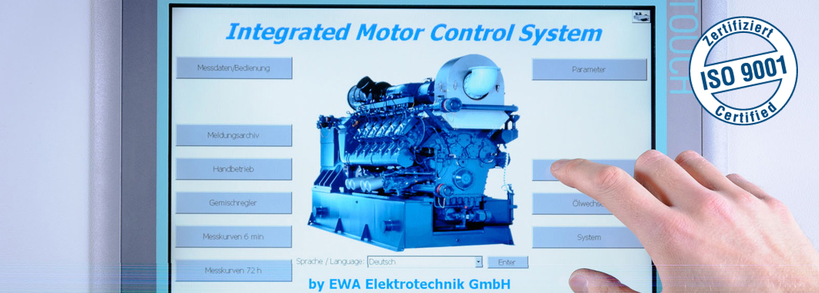
IMCS Integrated Motor Control System
The IMCS is a simple-to-operate and user-friendly integrated engine management system for gas engines.
System overview and functionality
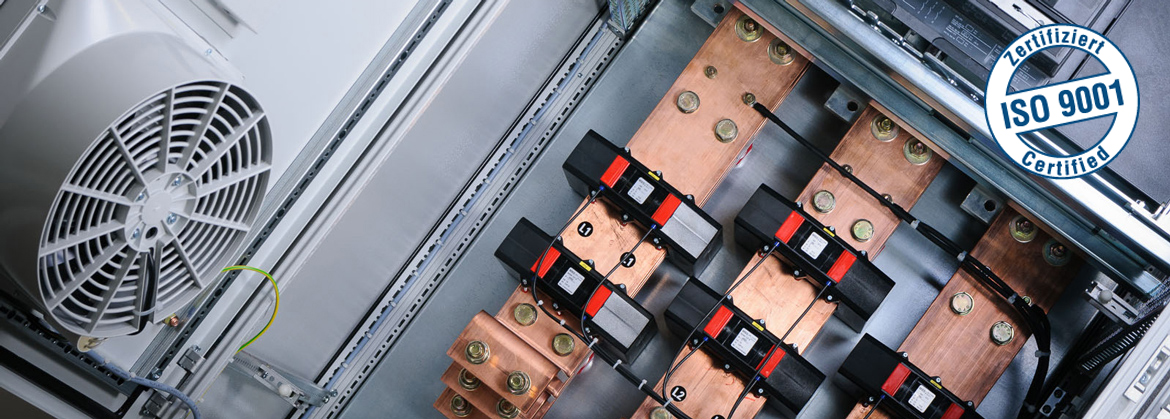
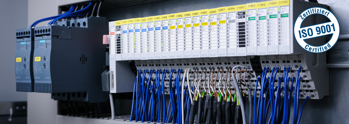
- The control system has been built exclusively on the basis of Siemens components. This ensures fast, long-term availability of spare parts, Siemens EC31 PLC
- 15’’ Siemens full graphic TFT touch panel. Type of protection for front panel: IP 65
- The touch panel is connected to the PLC via a Cat 6 data cable (Industrial Ethernet).
- Start and stop the generator set in Manual and Automatic mode (local/remote)
- 2 repeat start attempts if starting fails
- Control the power of the generator set
- Regulate the mixture with short settling time, for minimising harmful emissions
- Actuate the electronic ignition system with low-voltage distribution, with no mechanical wearing parts
- Actuate the electronic speed governor
- Regulate the temperature of the heating circuit
- Regulate the temperature of the mixture cooling circuit
- Regulate the temperature of the emergency cooling circuit
- Actuate the exhaust bypass valve
- Monitor all measured values and limit switches
- Information on warnings and alarms. Automatic stop in the event of alarms. First-up messages in the event of alarms, to simplify fault finding. Record all messages in an event archive. Display all active messages in a message archive.
- Clear and intuitive control with user guidance using softkeys
- Display measured values, messages, warnings and alarms
Control of the following functions:
- Manual/Automatic mode
- Engine start/stop, generator On/Off, preset power
- Auxiliary drive actuation
- Oil change
- Data acquisition for all important gen-set data, with two simultaneous temporal resolutions with the following features:
- Resolution of one second, recording depth of 6 minutes
- Resolution of 6 minutes, recording depth of 72 hours
- Simultaneous recording of max. 64 values, depending on the number of cylinders
- Recording is automatically stopped in the event of problems, to facilitate fault diagnosis
- Menu-guided selection of curves and graphic display on the touch panel. Data is saved even in the event of power failure.
- Standard interface to the higher-level control system
- Potential-free contacts for requests to the generator set
- 4-20 mA signal for power control
- Potential-free contacts for operation, warning and alarm
- Serial communication with the higher-level master controller or central control system
- Transmission of all important gen-set data (see message specification)
- Receipt of start/stop, nominal power, type of gas, remote acknowledgement
Data transmission to other control systems or computers via RK512 is fail-safe using the popular Siemens procedure 3964R. Standard interface TTY current loop 20 mA (choice of RS232 or RS485)
- Communication with the higher-level master controller or central control system via TCP/IP